Interact with the Real World: OpenXR Scene Understanding
OpenXR Scene Understanding Plugin Setup
Supported Unreal Engine version: 4.27 +
-
Enable Plugins:
- Please enable plugin in Edit > Plugins > Virtual Reality:
-
Disable Plugins:
- The "Steam VR" plugin must be disabled for OpenXR to work.
-
- Please disable plugin in Edit > Plugins > Virtual Reality:
-
-
Project Settings:
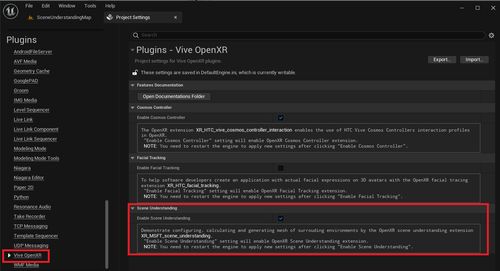
- Please make sure the “ OpenXR Scene Understanding extension ” is enabled, the setting is in Edit > Project Settings > Plugins > Vive OpenXR > Scene Understanding:
-
Project Settings:
Introduction to Blueprint Nodes for OpenXR Scene Understanding
-
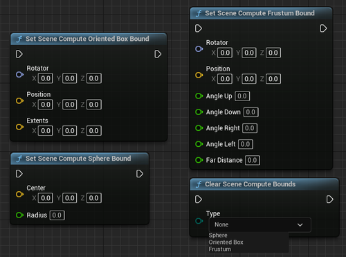
Used to limit the range that will be scanned
-
These bounding volumes are used to determine which scene components to include in the resulting scene.
- Set Scene Compute Oriented Box Bound : Set the bounds of the box shape.
- Set Scene Compute Sphere Bound : Set the bounds of the sphere shape.
- Set Scene Compute Frustum Bound : Set the bounds of the frustum shape.
- Clear Scene Compute Bounds: Before the game ends, you need to clear all bounds by calling Clear Scene Compute Bounds .
-
These bounding volumes are used to determine which scene components to include in the resulting scene.
-
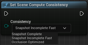
Controls the update speed of the scene and will affect the quality of the scene result
- This function will be trading off speed against the quality of the resulting scene.
-
- Set Scene Compute Consistency
-
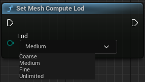
Identify the level of detail of meshes
- This function will identify the level of detail of visual mesh compute.
-
- Set Mesh Compute Lod
Show Scene Understanding scanned mesh in the game
-
Step1.
Essential Setup
-
- Creating an AR Session:
-
- The AR-related content needs to be set here because the OpenXR Scene Understanding uses OpenXRARTrackedGeometry to make the scanned meshes appear in the level. Unreal Setting up AR project Tutorial
- Create Data Asset: Content Browser > All > Content > click right mouse button > choose Miscellaneous > Data Asset
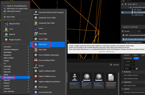
-
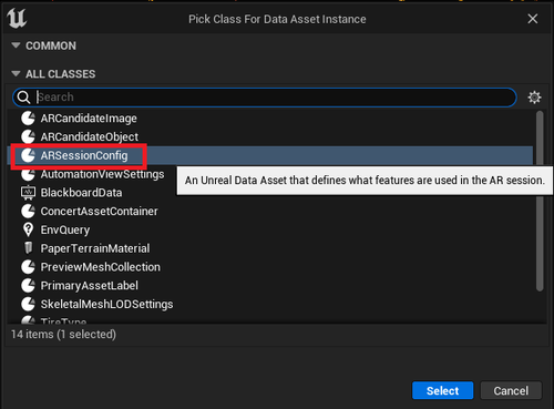
- After choose Data Asset , it will pop out “ Pick Class For Data Asset Instance ” window:
-
-
- Choose “ ARSessionConfig ” and press “ Select ”.
-
-
-
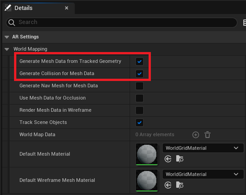
Open
ARSessionConfig
and enable some settings under Details Panel > AR Settiongs > World Mapping
- Enable Generate Mesh Data from Tracked Geometry
- Enable Generate Collision for Mesh Data
-
Open
ARSessionConfig
and enable some settings under Details Panel > AR Settiongs > World Mapping
-
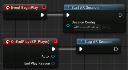
Open Level Blueprint and add
Start AR Session
and
Stop AR Session
- Remember to set the “ARSessionConfig” as input to Start AR Session.
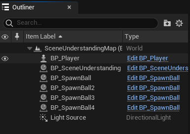
- Create a Blueprint for Scene Understanding and drag into the level.
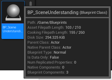
Step2. BP_SceneUnderstanding: Display scanned mesh in the level
- In this tutorial we choose Actor as the parent class.
-
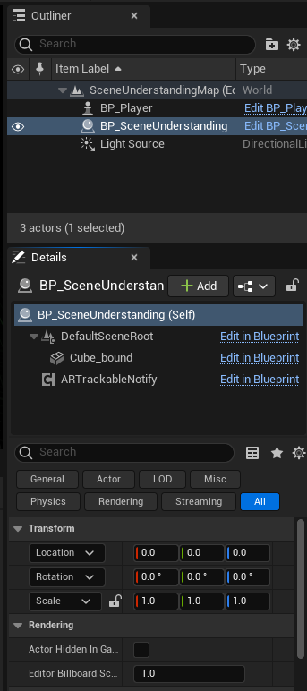
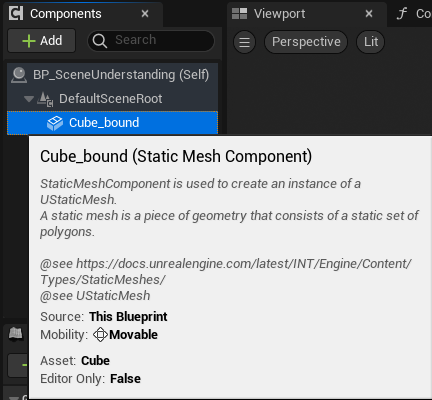
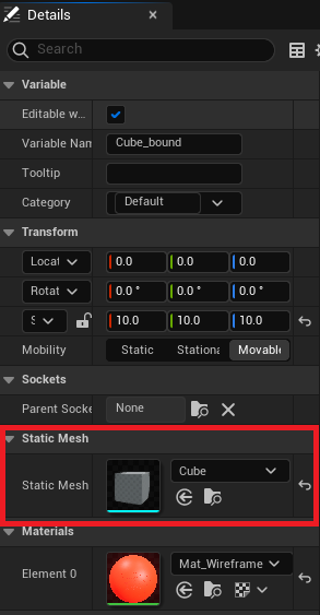
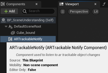
In Components panel:
- Add a Cube Static Mesh Component for Set Scene Compute Oriented Box Bounds .
- Add ARTrackableNotify Component in Components panel.
-
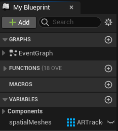
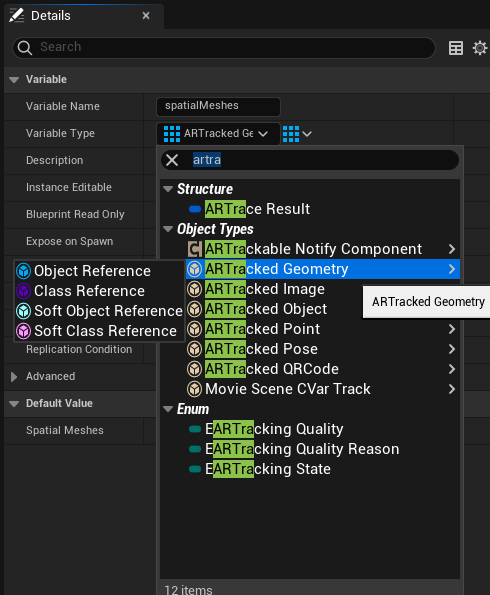
- Add a new variable and name it “ spatialMeshes ” with type “ ARTrackedGeometry Array ” in My Blueprint
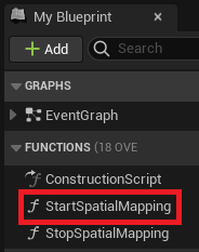
- Add a function and name it “ StartSpatialMapping ” in My Blueprint In this function, we need to call “ Toggle ARCapture ” function and set input “ On Off ” bool to true and “ Capture Type” to Spatial Mapping.
-
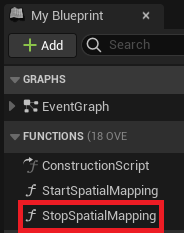
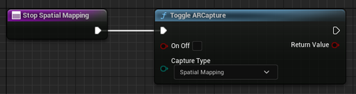
- Add a function and name it “ StopSpatialMapping ” in My Blueprint In this function, we need to call “ Toggle ARCapture ” function and set input “ On Off ” bool to false and “ Capture Type” to Spatial Mapping .
-
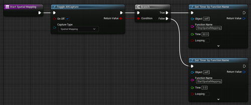
- Event BeginPlay : We will add some functions that affect the quality and area of the scanned mesh.
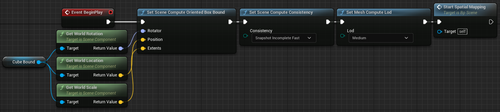
-
-
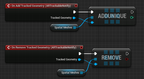
On Add/Remove Tracked Geometry (ARTrackableNotify):
- These two Events will control the number of mesh currently scanned.
-
On Add/Remove Tracked Geometry (ARTrackableNotify):
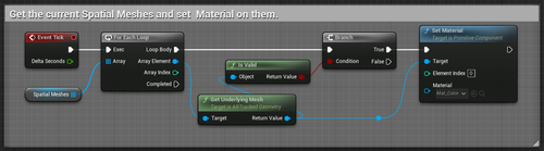
- Event Tick: You can get the current Spatial Meshes and Set Material on them.
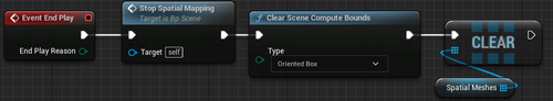
- Event BeginPlay: We will need to call Stop Spatial Mapping function and clear the bound you use at the beginning.
Result
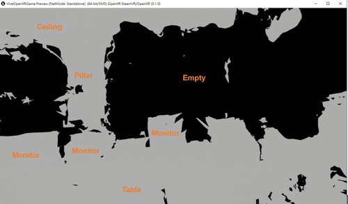
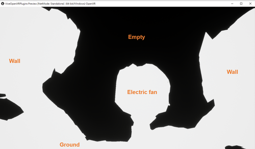
Note:
- White Area: meshes representing the real-environment objects.
- Black Area: no objects in the space.
Spawn balls and interact with generated meshes
This sample is currently only supported Unreal Engine version: 5.0+ .
Because the physics system used by the meshes generated is Chaos Physics .
-
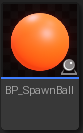
Create a Blueprint
- Create a Blueprint for the “Spawn ball” and drag it into the level.
- You can place as many as you want in the level.
-
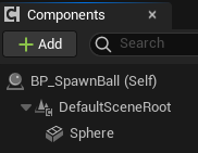
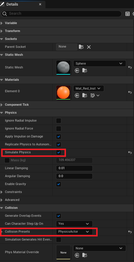
BP_SpawnBall: Make a sphere static mesh to simulate a physical fall.
- In Components panel: Add a Sphere Static Mesh Component to pretend the ball in Components panel.
- In Details panel: Enable Simulate Physics and make sure the Collision Presets is “PhysicsActor”
-
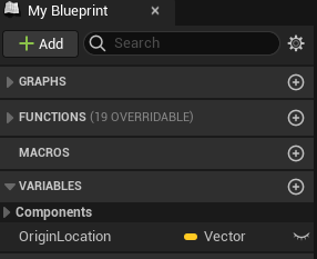
In
My Blueprint
panel:
- Add a variable to hold the origin location of the ball.
-
-
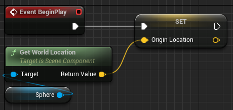
In
Event Graph
panel:
- Set the origin location of the ball when the game starts.
-
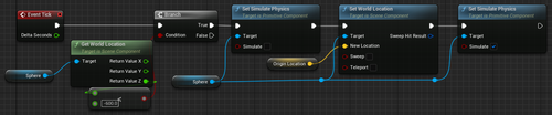
In
Event Graph
panel:
-
-
- Track the height of the ball in each frame, and reset its position if it is below -600.
-
Result
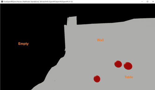
Note:
- Red Balls: Virtual Objects.
- White Area: It means that there are scanned meshes .
- Black Area: It means that there are no objects in the space.